Design Space Modeling Guide
Based on Section 3.4 of "System Architecture Optimization".
For an overview of modeling elements and how to use them, refer the following materials:


This guide provides more details and tips for modeling architecture design spaces. The recommended modeling process is as follows:
-
Identify boundary functions from functional requirements. Boundary functions should be specified such that they are solution-neutral from the point of view of the system of interest.
(Boundary) functions should be formulated as "[process] [operand]", where process is a verb applied to an operand (e.g. material, energy, or signal flow). Examples of functions are "accelerate air", "process signal", and "generate power". The following paper by Hirtz provides a useful database of solution-neutral processes and operands for functions of cyber-physical systems:
J. Hirtz et al. “A functional basis for engineering design: Reconciling and evolving previous efforts”. In: Research in Engineering Design 13.2 (Mar. 2002), pp. 65–82. doi: 10.1007/s00163-001-0008-3.
-
For each unfulfilled function, define how they can be fulfilled:
-
Use a concept element, mapping a (relatively) solution-neutral function to a (relatively) solution-specific function, to reduce the solution scope for the given design problem.
Normally there are multiple concepts that can fulfill a given function. To then reduce the solution scope, one or more of the alternative concepts can be disabled. This documents that the architect is aware of other concepts that can be used to fulfill the given function, however for the given design problem these concept(s) are not considered.
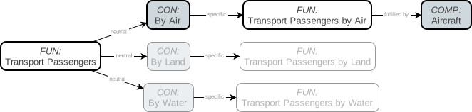
An example of this (shown in the figure below) is an aircraft manufacturer that wants to design a new aircraft to fulfill the high-level function "transport passengers". Passengers can also be transported over land or water, which can be documented as alternative concepts, next to transporting by air. Transporting over land and water can then be disabled, because they will not be considered by the aircraft manufacturer.
-
Use a function decomposition element, mapping one function to multiple functions, if the following three conditions are satisfied:
- "Parallelism" condition: satisfied if the function can be decomposed into two or more functions that either act in parallel, or are tightly-coupled in a loop without a clear starting point.
- "Solution-neutrality" condition: satisfied if the decomposed functions are as solution-neutral as the parent function, meaning they do not imply that some technology or solution is selected for fulfilling the parent function.
- "Compatibility" condition: satisfied if the fulfillment of the decomposed functions do not require major cross-tree incompatibility constraints to be defined later on.
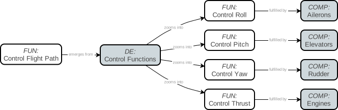
For example, to control the flight path of an aircraft, it should be possible to control pitch, yaw, roll, and thrust (shown in the figure below): the higher-level function "control flight path" can be decomposed into the lower-level functions "control pitch/yaw/roll/thrust". This mapping does not imply a specific control system solution, as all aircraft (including fixed-wing, rotorcraft, and lighter-than-air vehicles) need these functions. Also, they all act in parallel (there is no execution order between the four lower-level functions).
-
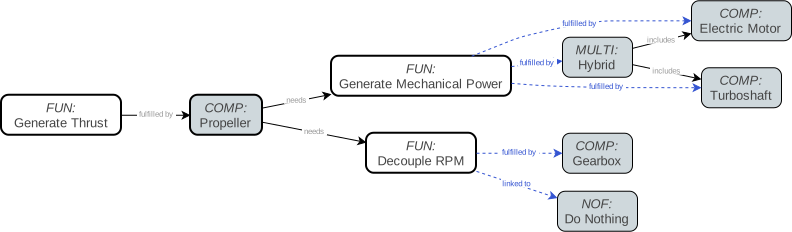
Use a component if some element of form can fulfill the function. Components represent the implementation of the system, and components should be named as nouns. Components may induce additional functions, which in turn need to be fulfilled. Components can both fulfill and induce multiple functions. An example is shown in the figure below.
Determining at what level of granularity to define components depends entirely on at what level architecture elements or architectural choices can be considered in the architecture evaluation code. For example, the function to "generate thrust" (for an aircraft) can be fulfilled by: a "propulsion system", a "turboprop", or a "propeller", in the order of increasing granularity. The "propeller" can be used to fulfill the function if there are alternatives for fulfilling the function, and/or if there are alternatives for fulfilling induced functions (e.g. electric motor or turboshaft for generating mechanical power), and if these alternatives can be captured in the evaluation code.
-
Use a multi-fulfillment element if multiple components can fulfill a function simultaneously. For example, in a flight control system, the roll can be controlled by both ailerons and spoilers; in a hybrid-electric aircraft propulsion system, mechanical power can be provided to propellers by both electric motors and turboshafts.
Multi-fulfillment elements can be used to define selection choice options that act at the same level as components (and concepts and function decompositions). For example, if there are two alternative components to fulfill a function, the multi-fulfillment can be used to define the third option of using both components simultaneously. For an aircraft propulsion system this mechanism can for example be used to model the choice between full-electric propulsion (electric motor), conventional propulsion (turboshaft), and hybrid-electric propulsion (both), as also shown in the figure above.
-
Use a non-fulfillment element to indicate the possibility for not fulfilling a function. This can for example be used for fulfilling secondary functions that may improve system performance, however at some cost. This indicates a trade-off which can be relevant at the system level.
An example would be the inclusion of a gearbox in a turbofan: the gearbox improves the propulsive efficiency of the turbofan, however at the cost of increased weight, manufacturing cost, and reduced reliability. This choice can be represented by a secondary function "decouple RPM", which can be fulfilled by a "gearbox" element or a non-fulfillment, as also shown in the figure above.
-
-
Use incompatibility constraints to declare that two elements (functions or components) are not allowed to exist in an architecture instance together. This can be useful if the involved components are derived in different function paths or decomposition trees.
Incompatibility constraints are also useful if multiple components represent options in two or more architectural choices. If left unconstrained, each architectural choice is independent of each other and as such it can happen that more than one of the components is selected in an architecture, each for fulfilling different functions. If that does not represent a realistic architecture, then incompatibility constraints can be defined between the components.
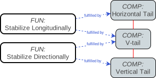
An example is if for a flight control system, directional stability can be achieved by a vertical tail or by a V-tail, and longitudinal stability can be achieved by a horizontal tail or by a V-tail as well (shown in the figure below). The combination of a V-tail and either a vertical or horizontal tail does not make sense, however if left unconstrained can be selected as an architecture instance.
-
Use subsystems to group elements logically belonging together, especially if the group as such can be instantiated multiple times in an architecture.
For example, elements inside a propulsor unit can be grouped into a propulsor subsystem, if also other elements of the aircraft are modeled at a similar level of detail, or if the propulsor as a whole can instantiated multiple times. This example is shown in the figure below, including a function fulfillment choice within the subsystem.
Subsystems can be nested recursively to enable grouping elements at multiple levels of system decomposition.

-
Once components have been defined, system, function and component characterization options can be defined:
-
Component instantiation represents cases where the component can be included multiple times in an architecture, and where the number of instances is a choice. For example, the number of engines of an aircraft can be a choice.
-
System, function and component design variables represent sizing or property parameter choices, and can either be continuous, representing a number between two bounds, or discrete, representing a choice from a finite set of options. Design variables can either be defined for the component as a whole, or for each component instance separately. Examples of design variables are the bypass ratio of a turbofan (a continuous design variable) or the number of compressor blade rows of a linear compressor (a discrete design variable).
-
Other characterization options include the definition of static inputs, for example representing assumptions or static requirements, and design constraints. Examples include defining environmental conditions as static inputs or defining material stress limit constraints.
Whether to use discrete design variables or alternative components for fulfilling a function depends on the level of granularity appropriate for the design problem. It is recommended to use alternative components if the different components induce different functions and/or contain different characterization options as described above. For example, a choice between two types of turbofans can be modeled using a turbofan component with a discrete design variable selecting between the different types. However, a choice between a turbofan, a turboprop, and other propulsion technologies might be more appropriately modeled using alternative components, as they might induce different functions to be fulfilled by other aircraft systems.
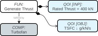
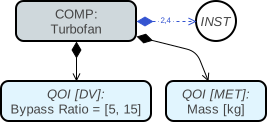
Static inputs, design variables, and design constraints are defined using Quantity of Interest (QOI) elements. QOI elements also define output metrics, optionally used as objectives or inequality constraints. The figures below shows an example of function and component characterization. The generate thrust function has two QOIs associated to it: a TSFC (Thrust-Specific Fuel Consumption) minimization objective and a rated thrust static input. The turbofan component has an instantiation choice (2 or 4 instances), and it has two QOIs associated: a bypass ratio continuous design variable and a mass output metric.
-
-
Architectural choices at the component-instance level or in instances of the same subsystem are independent of each other. If this should not be the case, the choices can be constrained by adding a choice constraint. The following types of choice constraints are available:
-
"Linked": ensures that all choices are assigned the same option. This constraint can be applied if for example multiple propulsor subsystems exist, and all subsystems should either have turbofans or electric motors.
-
"Permutations": ensures that no choice is assigned the same option. The result is that the set of constrained choices effectively becomes a permutation choice.
This can be useful if for example a selection of properties across component instances is fixed, however they may be distributed over components in different ways (i.e. permutations). It can also be used if there are many components for fulfilling some function across several subsystem instances, and each component can only be used in a specific subsystem once.
-
"Unordered combinations": ensures that choices are assigned an equal or later option. This can be used to model situations where component-level or subsystem-level choices may have different options assigned over their instances, however where permutations (i.e. different ways of "ordering") of a set of options should not be considered.
This can for example be used if it is allowed to have a mix of turbofans and electric motors across different propulsor subsystems, and only the number of turbofans and electric motors influences the system performance (i.e. not the assigned subsystem index).
-
"Unordered non-replacing combinations": ensures that choices are assigned a later option. The behavior is similar to the unordered combinations constraint, however prevents choices from having the same option assigned.
This can be useful if there are many components for fulfilling some function across several subsystem instances, each component can only be used in a specific subsystem once, however permutations of technology assignment do not influence system performance.
-
-
Use port elements to model connection, assignment, and/or allocation choices between (sets of) components.
Such choices are appropriate when the components to be connected are included for fulfilling different functions (or as part of different function paths). For example, a turbofan might both have the primary function to generate thrust and a secondary function to generate electrical power. The primary function derives turbomachinery components and shafts with multiple compression stages. The secondary function might derive an electrical generator. The electrical generator is then connected to one of the shafts: which shaft instance to connect to can be modeled using a port element.
Ports can also be useful to further elaborate how components within a function path are connected. For example, some power consumer (e.g. a flight control surface) might induce the function to provide power, which is fulfilled by a power distribution system. However, there are multiple control surfaces and multiple distribution systems for redundancy, and assigning the distribution systems to the control surfaces is not a trivial problem and is therefore relevant to be included in the architecture design space. This assignment choice can be modeled using a port, see the figure below. Constraints can be added to for example ensure that each control surface is assigned to at least one distribution system, and each distribution system supplies at least one control surface with power.
Ports use connection choices, which are more powerful for modeling architecture decision patterns. It is for example possible to define connection, assignment, downselection, or permutation choices.

-
Iterate until all functions are fulfilled, and elements are defined and characterized at the appropriate level of granularity.
By modeling function fulfillment at the appropriate level of granularity, the "primary value paths" should emerge. A primary value path is the chain of functions that delivers the main value of the system (i.e. fulfills the boundary functions) by executing them sequentially or in parallel. Note that primary value paths are properties of architecture instances, so architecture design spaces may contain multiple value paths.
For more details, the reader is referred to Chapter 8 of:
E. Crawley, B. Cameron, and D. Selva. System architecture: strategy and product development for complex systems. England: Pearson Education, 2015. ISBN: 978-0-1339-7534-5.
That chapter also includes helpful questions to ask during the architecture modeling process, and it includes guidance on the level of detail that should be modeled for a given design problem.
-
Define system-level performance metrics to drive the architecture optimization loop. Performance metrics are defined using QOI elements, and can either take the role of minimization or maximization objectives, design constraints, or generic metrics:
-
Objectives are the main drivers of the optimization, and normally represent system-level metrics. They can be assigned to the top-level system or an appropriate boundary function, however they at least should be assigned to some element that is present in all architecture instances: otherwise architecture instances cannot be compared to each other.
-
Design constraints represent some threshold requirement to be met. Constraints do not have to necessarily always exist, for example if they constrain the behavior of a particular component only.
-
Generic metrics do not drive the optimization, however are useful for verifying evaluation results. They can for example represent internal calculation results (to verify that the final metrics are calculated correctly), or component-level calculation results (to verify that system-level aggregated metrics are calculated correctly).
The figures of point 5 show examples of QOIs used as objectives and output metrics.
-
-
Verify that the evaluation code is sensitive to the modeled architecture design choices: each choice should influence one or more performance metrics. If for a given choice this is not the case, there are two options:
- Remove the choice by disabling or removing associated model elements; or
- (Plan to) modify the evaluation code to be sensitive to the choice.
-
Verify that the architecture design space behavior is correctly implemented by verifying choices, adding choice constraints if needed, and manually generating architecture instances.
The manual architecture generation process takes the architecture choice-by-choice from the design space model towards an architecture instance. By going choice-by-choice, the architect can verify that choices appear in a logical order, that the choice hierarchy is correctly implemented, that the correct options for different combinations of choices are present, and that any choice constraints are implemented correctly.